
How to Connect Factory Wiring to Android Head Unit (100% Working)
Upgrading your factory radio? Learn how to connect factory wiring to Android head unit systems using plug-and-play adapter harnesses, resolve reversed yellow/red power pins, and configure steering wheel and reverse camera triggers without cutting OEM wires.

Preparing to connect factory wiring to android head unit sockets without cutting or splicing original copper leads protects your dashboard electronics and preserves original factory wiring harnesses.
Vehicle manufacturers engineer dashboard wiring using proprietary multi-pin locking plugs designed exclusively for OEM stereos.
Aftermarket Android touchscreen units, by contrast, utilize an industry-standard 16-pin power and speaker socket built directly into the rear aluminum heatsink.
Attempting to hardwire an aftermarket radio by snipping factory connectors destroys vehicle resale value, voids electrical warranties, and introduces high-resistance joints.
These poor connections often trigger phantom parasitic battery drains that leave vehicles stranded.
Under modern automotive electrical standards based on ISO 10487 harness configurations, aftermarket stereos use standardized color coding.
This universal standard makes slicing factory copper completely unnecessary on modern dashboards.
With an inexpensive vehicle-specific adapter harness and a digital multimeter, you can bridge your car’s factory loom directly into the stereo’s 16-pin port without stripping a single factory wire.
Here are five practical workshop steps to safely connect factory wiring to android head unit terminals and retain factory steering wheel controls, reverse cameras, and clean audio.
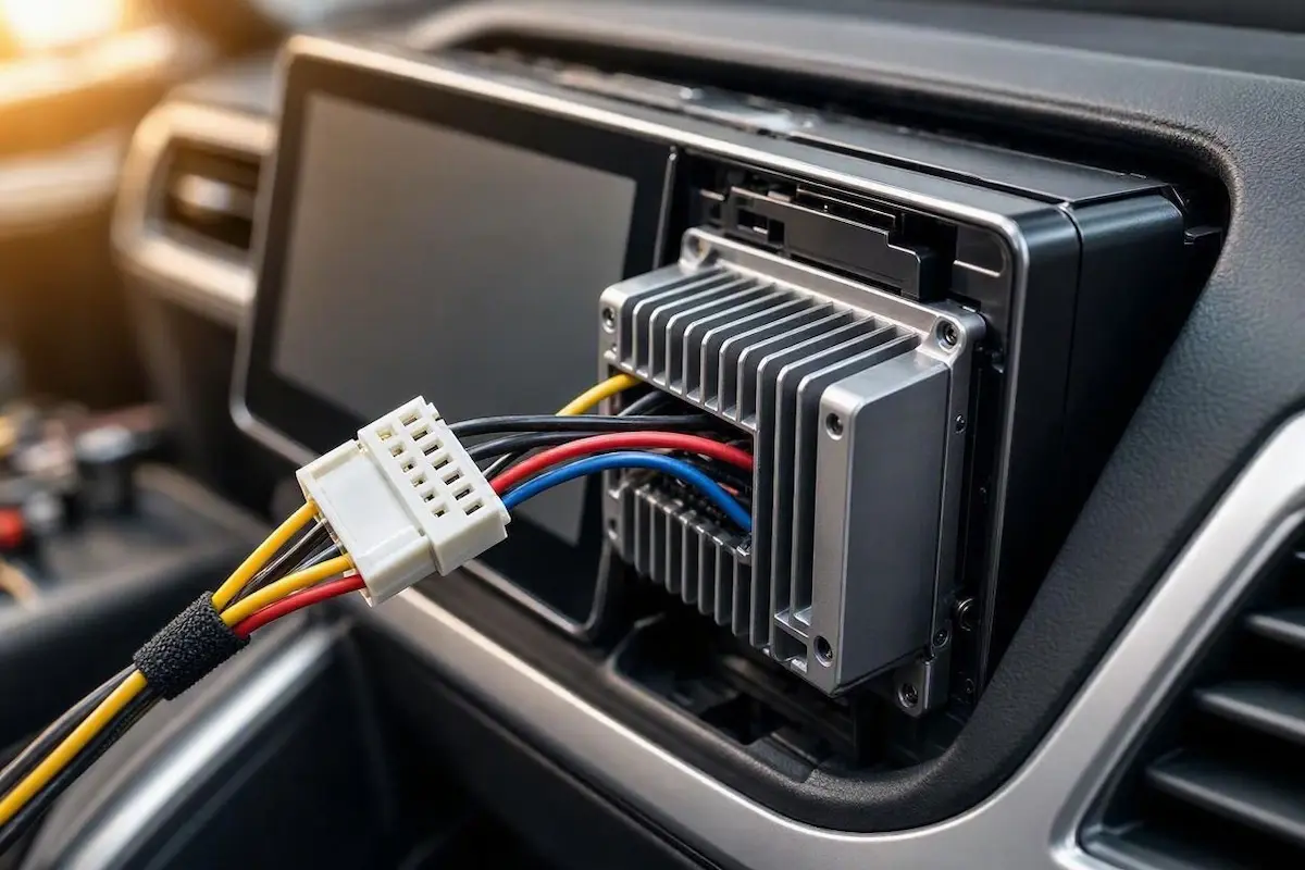
Diagnostic Matrix: How to Connect Factory Wiring to Android Head Unit
Before matching wires, use our workshop pinout matrix to cross-reference universal 16-pin aftermarket wire functions against factory vehicle signals as you connect factory wiring to android head unit terminals:
| Wire Color | Standard Pin Function | Operational Role & Bench Test Method |
|---|---|---|
| Yellow | Constant +12V Battery (B+) | Maintains volatile memory, clock, and sleep state; reads 12V with key removed. |
| Red | Switched +12V Accessory (ACC) | Triggers system wake/boot; reads 12V only when ignition key is turned to ACC/ON. |
| Black | Chassis Ground (GND) | Primary electrical return path; must measure under 0.2 Ohms resistance to bare chassis metal. |
| Orange / Orange-White | Illumination (ILL / ILLUMI) | Signals night mode to dim screen; receives +12V when parking lights or headlights activate. |
| Pink or Brown | Reverse Gear Detection (BACK / REV) | Forces display to switch to backup camera; receives +12V from vehicle reverse light circuit. |
| Blue / Blue-White | Amplifier / Antenna Remote (AMP-CONT) | Outputs +12V (max 500mA) to energize OEM external amplifiers or roof antenna boosters. |
| White & White/Black | Front Left Speaker (+ / -) | Solid is Positive (+), Striped is Negative (-); feeds 4-Ohm front driver door speaker. |
| Gray & Gray/Black | Front Right Speaker (+ / -) | Solid is Positive (+), Striped is Negative (-); feeds 4-Ohm front passenger door speaker. |
| Green & Green/Black | Rear Left Speaker (+ / -) | Solid is Positive (+), Striped is Negative (-); feeds 4-Ohm rear driver door speaker. |
| Purple & Purple/Black | Rear Right Speaker (+ / -) | Solid is Positive (+), Striped is Negative (-); feeds 4-Ohm rear passenger door speaker. |
Step 1: Use Vehicle-Specific Plug-and-Play Couplers (Never Cut OEM Leads)
The cleanest method to connect factory wiring to android head unit platforms without cutting factory copper is utilizing a vehicle-specific adapter harness coupler.
These adapter harnesses consist of two pre-molded plastic connectors bridged by color-coded wires.
One side features an OEM-style male plug that clicks directly into your car’s factory dashboard connector.
This plug locks securely into place with the original plastic latch mechanism.
The opposing side terminates in a universal 16-pin female block that plugs straight into the Android head unit chassis:

- Sourcing the Coupler: Search online retailers or local audio distributors using your exact vehicle specifications:
[Car Make, Model, Year] to 16-pin Android head unit harness. - Preserve OEM Value: Using a plug-and-play coupler leaves the vehicle’s original factory harness completely unmolested. If you sell the vehicle in the future, you can unplug the Android screen and snap the factory radio back into the dashboard in five minutes.
- Eliminate Intermittent Shorts: Hand-twisted wires covered in vinyl electrical tape inevitably loosen from road vibrations and summer cabin heat. Molded couplers provide strain relief and locked terminal pins that prevent loose connections permanently.
Using a coupler guarantees a reliable path to connect factory wiring to android head unit ports while protecting factory electrical systems.
RELATED TROUBLESHOOTING GUIDE
Step 2: Verify Yellow (B+) Constant and Red (ACC) Switched Lines with a Multimeter
The single most frequent wiring fault encountered when learning how to connect factory wiring to android head unit pinouts is the swapped 12V constant and switched ignition lines.
Budget adapter harnesses from overseas manufacturers frequently reverse the positions of the Yellow (12V Constant B+) and Red (12V Switched ACC) wires.
When these lines are swapped, the stereo behaves abnormally:
- The Swapped Power Symptom: If your Android stereo takes 40 to 60 seconds to perform a cold boot every time you start the engine, loses its clock time, or wipes your saved radio equalizer settings, the memory wire is losing constant battery voltage.
- The Parasitic Drain Symptom: If the stereo remains powered on and drains your vehicle battery even when the key is completely removed, the switched ignition lead is receiving continuous 12V battery power.
- Set a digital multimeter to DC Volts (20V range). Touch the black test probe to a bare unpainted metal bolt on the vehicle firewall.
- Remove the vehicle key from the ignition. Backprobe the Yellow wire on your harness coupler. The meter must read between 12.4V and 12.8V. If it reads 0V, your constant line is miswired.
- Insert the vehicle key and turn it to the ACC (Accessory) or ON position. Probe the Red wire. The meter must read 12.0V+ with the key on, and drop to 0.0V the exact second the key is switched off.
- The Workshop Fix: If the lines are reversed, disconnect the quick-disconnect bullet connectors on the harness (or release the terminal locking tabs inside the plastic plug) and swap the Yellow and Red leads. If your stereo loses time despite correct wiring, read our guide on fixing Android car stereo time reset issues.
Properly isolating constant power ensures that when you connect factory wiring to android head unit plugs, internal settings persist across ignition cycles.
⚠️ Crucial Ground Warning: Never rely solely on the factory harness ground wire if you plan to install high-power speakers. Factory ground wires are often thin 20-AWG leads. For maximum amplifier stability, splice an auxiliary 14-AWG wire into the Black ground lead and bolt it directly to bare chassis steel using a star washer to prevent the car stereo turns off when volume is high fault.
Step 3: Determine Between Resistive Analog vs. Active CANbus Decoder Boxes
Before completing your installation, deciding how to connect factory wiring to android head unit systems depends on whether your vehicle uses simple analog wiring or a digital multiplexed network.
Vehicle architectures handle auxiliary triggers (such as steering wheel controls, reverse gear detection, and illumination dimming) in one of two ways:
- Passive Analog Couplers (Key 1 / Key 2): Found in older vehicles and base trims (such as older Toyota, Honda, Nissan, and Suzuki models). These cars use simple resistive voltage dividers for steering wheel buttons. Pressing a button sends a specific analog resistance value down the KEY 1 or KEY 2 wire to the head unit. You do not need a digital decoder; simply wire Key 1 and Ground, then map the buttons inside the stereo’s built-in “Steering Learn” app.
- Active CANbus Decoder Boxes: Mandatory for modern vehicles (including Ford, Volkswagen, GM, Jeep, BMW, and premium trims). In these vehicles, the factory radio does not receive a physical 12V accessory wire, reverse light wire, or analog steering lines. Instead, all commands travel as digital binary packets over high-speed CAN-High and CAN-Low twisted pairs.
- Configuring the Decoder: If your car uses CANbus, your plug-and-play harness will include a small black plastic decoder module (manufactured by Raise, Simple Soft, or Hiworld). You must plug the decoder into the harness, access Car Settings → Factory Settings on the stereo, and select your exact vehicle make, model, and year to allow the microcontroller to decode digital data packets. Review our complete guide to configure Android car stereo CANbus decoder settings for step-by-step programming.
Identifying this network protocol is an indispensable step to connect factory wiring to android head unit motherboards without throwing vehicle fault codes.
STEERING WHEEL CONTROL GUIDE
Step 4: Wire Auxiliary Reverse Camera, Illumination, and Antenna Triggers
Once primary operating power and speaker lines are established, the process to connect factory wiring to android head unit triggers requires testing auxiliary control leads:
- Reverse Camera Switching Line (BACK / REV): The Pink or Brown wire in the 16-pin harness triggers the head unit to instantly switch display priority to the backup camera RCA video feed. If installing an aftermarket camera, connect the short red trigger pigtail coming out of the yellow video RCA cable directly to this BACK wire. When you shift into reverse, the vehicle backup light energizes this line with +12V, commanding the screen to show the camera feed. If your screen shows static, check our walkthrough on fixing reverse camera no signal errors.
- Factory Antenna Booster / External Amp (AMP-CONT): The solid Blue or Blue/White wire outputs a +12V turn-on signal (limited to 500mA) when the stereo powers on. Many modern vehicles incorporate an active phantom antenna amplifier embedded in the rear glass. If you forget to connect the Blue wire to your vehicle harness adapter’s antenna booster lead, your FM/AM radio reception will be full of static.
- Illumination Dimming (ILL): The Orange or Orange/White wire dims the Android touchscreen backlight when exterior lights are switched on. In modern cars utilizing Pulse Width Modulation (PWM) cluster dimmers, connect this wire only if your coupler includes a dedicated analog filter, preventing android car stereo screen flickering issues caused by PWM voltage pulsing.
Completing these trigger lines makes your effort to connect factory wiring to android head unit systems operate just like an original OEM infotainment setup.
Step 5: Isolate Unused Leads and Secure Harness Bundles
The final mechanical checkpoint when you connect factory wiring to android head unit harnesses is isolating unassigned wires to prevent accidental short circuits behind the dashboard cavity.
Many universal 16-pin harnesses include extra wires designed for specific vehicle options that your car may not utilize:
- Tape Off Tel-Mute and Brake Leads: The Brown wire labeled TEL MUTE mutes all audio when connected to ground. If this bare copper lead touches the metal radio chassis, your speakers will go completely dead. Always cap unused leads with heat-shrink tubing or quality electrical tape. If you experience unexpected muting, consult our guide on fixing Android car stereo no sound issues.
- Bypass the Parking Brake Wire: The wire labeled BRAKE or PARKING is designed to lock out video playback while driving. Connecting this wire permanently to the Black chassis ground wire grounds the safety circuit, allowing passengers to view navigation and video without annoying parking brake lockouts.
- Eliminate Dashboard Rattles: Bundle all loose RCA breakout leads, USB extension cables, and CANbus boxes together using automotive cloth tesa tape. Wrapping the harness bundle prevents sharp plastic edges from rattling against steel dash crash bars over rough roads. If your unit is stuck cycling on reboot, check our guide to fixing an Android car stereo boot loop.
Taking time to connect factory wiring to android head unit sockets using dedicated couplers preserves your vehicle harness, protects factory warranties, and ensures reliable audio performance.
By verifying constant battery lines with a multimeter, selecting the proper CANbus or analog decoder, and insulating auxiliary trigger leads, you eliminate wiring gremlins permanently.
Following this structured workshop procedure ensures you can connect factory wiring to android head unit motherboards cleanly, delivering an OEM-grade installation that performs flawlessly on every drive.
Frequently Asked Questions (FAQ)
Can I connect factory wiring to an Android head unit without an adapter harness?
While physically possible to connect factory wiring to android head unit terminals by cutting factory plugs and splicing wires manually, this is strongly discouraged in professional workshops. Cutting factory wiring destroys vehicle resale value, voids electrical warranties, and introduces high fire risks from loose splices. Using a dedicated vehicle-specific plug-and-play coupler costs less than $15 and preserves factory wiring completely.
Why does my Android head unit stay on when the ignition key is removed?
This issue indicates that the Red (Switched ACC) wire is receiving constant 12V battery power instead of switched accessory power. This is commonly caused by reversed Red and Yellow pins on budget adapter harnesses, or an improperly configured CANbus decoder box that fails to send sleep commands across the data network.
What do KEY1 and KEY2 wires connect to on an Android car stereo?
KEY1 and KEY2 are resistive analog inputs designed to measure voltage drops from factory steering wheel control buttons on non-CANbus vehicles. When you press a steering button, it sends a specific resistance value down the Key line, which you can map to volume, track skip, and call functions using the stereo’s built-in Steering Learning app.
Why does my radio lose its clock time every time I turn off the car?
Losing saved radio stations, equalizer presets, and clock time occurs when the Yellow (Constant +12V B+) wire is wired to a switched ignition circuit rather than an unswitched battery line. Swapping the Red and Yellow bullet connectors on your adapter harness restores continuous power to the internal memory registers.